Sealing Technology
Technical Information on Sealing Technology
1. Installation Instructions
1.1 ROD SEALS AND WIPERS
Surface finish
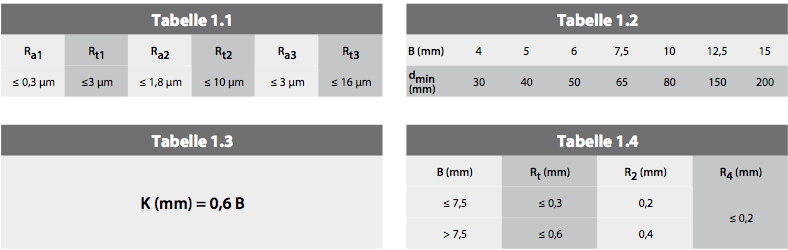
The roughness values given in Table 1.1 must be observed in both the Ra and Rt ranges.
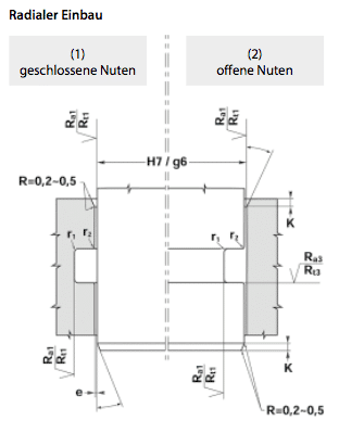
Open or closed grooves
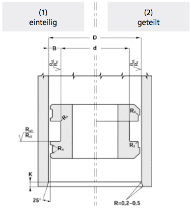
Table 1.2 can be used to determine whether installation in closed grooves (1) is possible. For a given cross‑section B we recommend installation in open grooves (2) if the rod diameter is smaller than the minimum diameter (dmin).
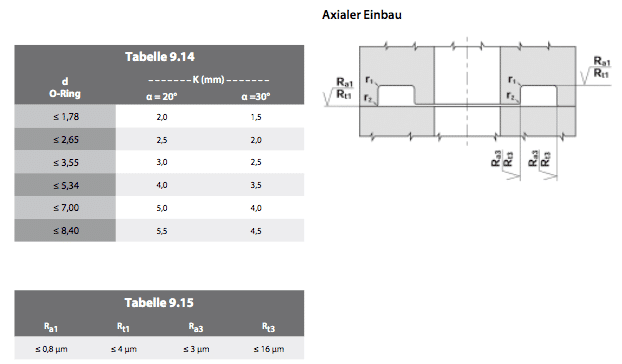
Chamfers
Table 1.3 specifies the chamfer lengths K that must be observed.
Radii
Sharp edges must be avoided. Table 1.4 lists the radii that must be observed.
1.2 PISTON SEALS AND GUIDE RINGS
Surface finish
The roughness values given in Table 1.1 must be observed in both the Ra and Rt ranges.
Single‑piece or multi‑piece pistons
For each seal profile, refer to the “Installation” section provided in this catalogue for the individual seal.
Chamfers
Table 1.3 specifies the chamfer lengths K that must be observed.
Radii
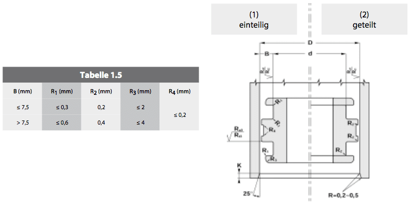
Sharp edges must be avoided. Table 1.5 lists the radii that must be observed.
õ
2. Proper Assembly
If hydraulic seals are not installed correctly, numerous problems can occur due to seal damage. Below are some important tips to avoid these issues:
- Check groove diameters, tolerances, surface finish and chamfers using the data in this catalogue.
- During assembly, the seal must not come into contact with sharp edges, drilled holes or threads.
- All metal parts must be perfectly clean, free of chips, welding splatter and defects.
- All seals must be lubricated before installation with the same fluid used in the hydraulic circuit or with a compatible fluid.
- Never use sharp‑edged tools for installation. Do not deform the seals for an extended period.
- Finally, make sure the seal is installed in the correct orientation relative to the pressure direction and that all other parts are mounted correctly.
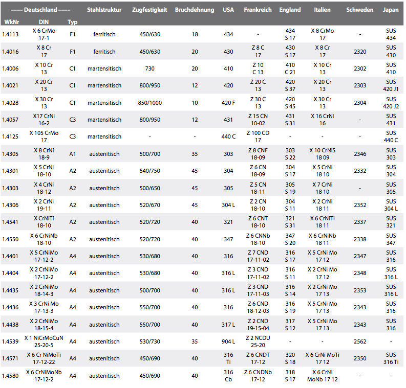
3. International Comparison Table for Corrosion‑Resistant Steels
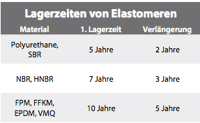
4. Storage Conditions for Elastomers
- Max. 25 °C
- No direct heat sources nearby
- No direct sunlight
- Install low‑UV lighting
- Max. 60 % relative humidity – avoid condensation
- No ionising radiation or ozone exposure, e.g. from welding
- Store in PE bags or original packaging
- Do not store hanging, e.g. on hooks, etc.
INSPECTION AFTER INITIAL STORAGE PERIOD
Visual inspection:
- Deformation, cuts, cracks on the surface (use 10× magnification)
- Hardening, softening, discoloration, contamination
- Permanent deformations, creases, flat spots
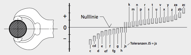
5. Tolerances and Fits
Fit table for ISO tolerances – basic hole / basic shaft system according to ISO 286.
Nominal dimensions for shafts follow DIN 7160, for bores DIN 7161.
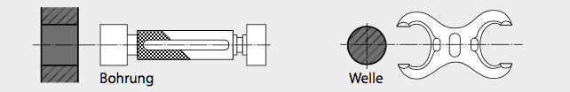
DIMENSIONS FOR BORES AND SHAFTS
The ISO system for tolerances and fits applies to all linear dimensions such as external, internal and diametral sizes, lengths, widths, heights and thicknesses. All dimensions are referenced to 20 °C.
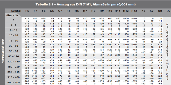
Tables 5.1, 5.2 and 5.3 list a selection of proven tolerances in tool‑ and mould‑making, which are also preferably used for HASCO standard parts. These tolerances are indicated in our technical documents to show precise execution and are advantageous in many other fields as well.
TOLERANCES FOR INTERNAL DIMENSIONS (BORES)
TOLERANCES FOR EXTERNAL DIMENSIONS (SHAFTS)
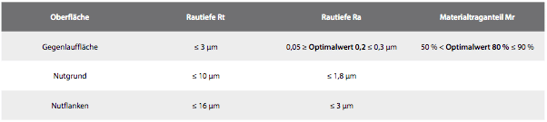
6. Surface parameters for installation spaces
General requirements for seal installation spaces.
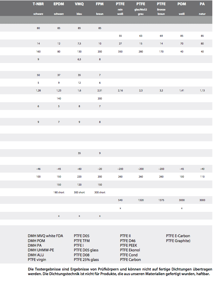
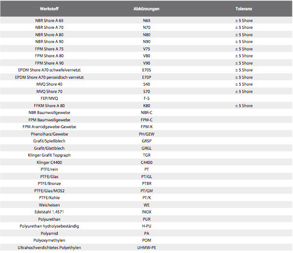
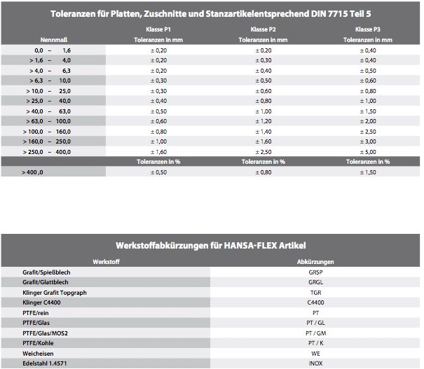
7. Material abbreviations for HF seal items
8. Bushings
8.1 General
Technical data
To aid understanding, we first clarify some key technical data used throughout. We consider a bushing with an inner diameter d and a width L.
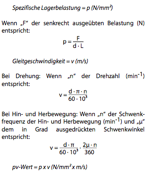
Service‑life calculation
Service life depends on specific bearing load, sliding speed, operating temperature and shaft material (surface finish and hardness). On request we can provide a life calculation, which is however only a guide value.
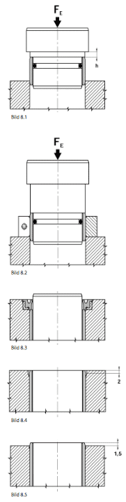
Installing bushings
For bushings with an outer diameter up to 50 mm use the basic method shown in Fig. 8.1. By machining the housing face to height h the bushing can be pressed to exact depth h.
For OD > 50 mm, use an auxiliary ring as in Fig. 8.2. We can calculate the insertion force FE on request.
Installation principle
We recommend protecting bushings with seals type SWP or radial shaft seals (Fig. 8.3) to prevent contamination. To avoid stress concentrations at the bushing edges, machine chamfers or let the bushing protrude (Fig. 8.4 & 8.5).
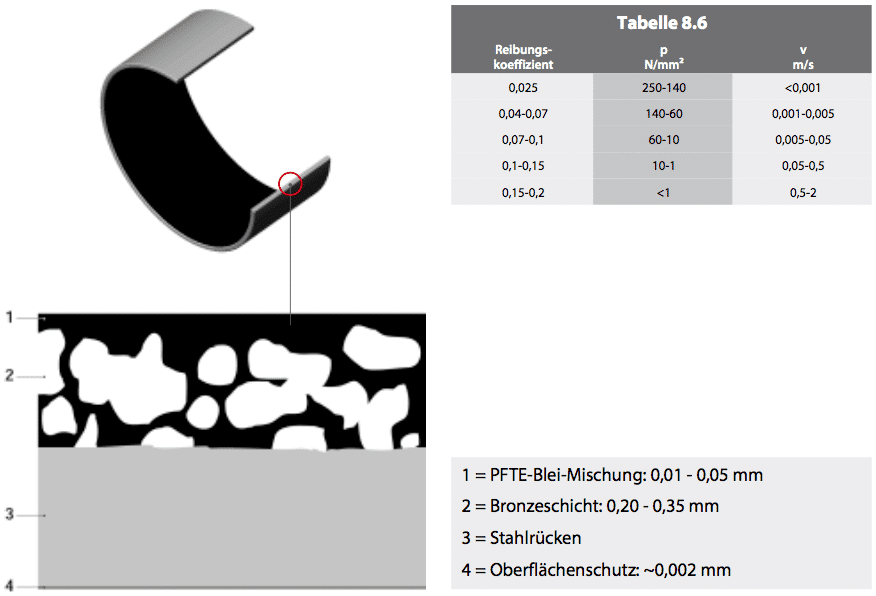
8.2 Maintenance‑free bushings TYPE BK‑1
Construction
BK‑1 consists of a steel backing (3) onto which a porous bronze layer (2) is sintered. A PTFE‑lead mixture (1) is then rolled into the bronze. The steel backing is tin‑ or copper‑plated externally for corrosion protection (4).
Features
- Suitable for dry running and maintenance‑free
- Absorbs noise and vibration
- Hydrodynamic operation possible
- High permissible load
- Good chemical resistance
- Favourable friction behaviour – no stick‑slip
- Wide temperature range
- High sliding speed
- No water absorption
- Minimal clearance in operation
- Extremely space‑saving
Applications
BK‑1 is suitable for translational, rotational and oscillating movements.
Application examples
- Rod guides for pneumatic and hydraulic cylinders
- Eye mounts of pneumatic and hydraulic cylinders
- Conveyors, textile machinery, automobiles, …
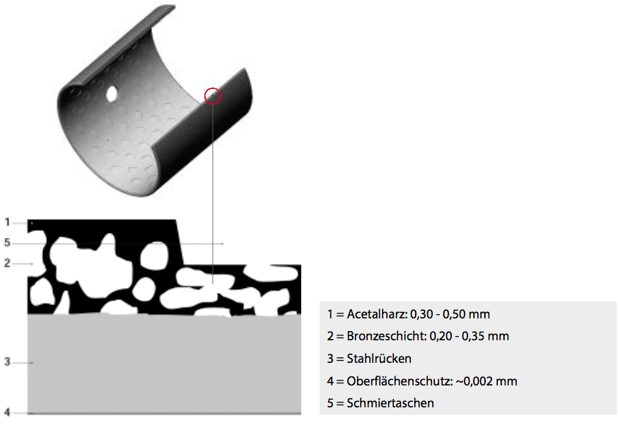
8.3 Re‑lubricatable bushings TYPE BK‑2
Construction
BK‑2 has a steel backing (3) with porous bronze (2), into which acetal resin POM (1) is rolled. The backing is tin‑ or copper‑plated (4). Lubrication pockets (5) are embossed in the sliding layer.
Features
- Maintenance‑free operation
- Noise and vibration damping
- Can be re‑lubricated
- Hydrodynamic operation possible
- High permissible load
- Good friction properties
- High sliding speed
- No water absorption
- Ideal where a continuous oil film is hard to achieve
- Minimal clearance in operation
- Extremely space‑saving
Applications
BK‑2 is suitable for rotational and oscillating movements. An initial grease charge is recommended; continuous lubrication greatly extends bearing life.
Application examples
- Eye mounts of pneumatic and hydraulic cylinders
- Agricultural equipment
- Bulk‑material conveyors
- Civil‑engineering machinery, …
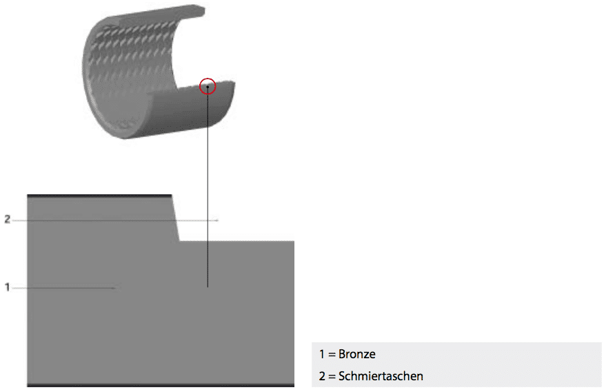
8.4 Bronze bushings TYPE BK090
Construction
BK090 is made entirely of CuSn8 bronze from calibrated and rolled strip. The whole sliding surface features diamond‑shaped lubrication pockets that act as reservoirs, progressively releasing lubricant during operation. Provide a lubrication hole for re‑lubrication.
Features
- Maintenance‑free operation
- Re‑lubricatable
- Suitable for dirty environments
- Shock‑ and vibration‑resistant
- High permissible load
- Good friction properties
- No water absorption
- Minimal clearance in operation
- Extremely space‑saving
Applications
BK090 is suitable for rotational and oscillating movements. Initial grease charge is recommended; continuous lubrication greatly extends bearing life.
Application examples
- Eye mounts of hydraulic cylinders
- Forestry equipment
- Agricultural machinery
- Lifting and conveying systems
- Civil‑engineering equipment, …
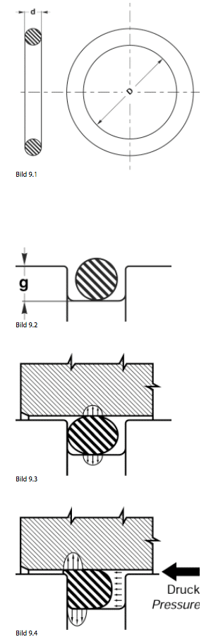
9. O‑Rings
9.1 DESCRIPTION OF O‑RINGS
The O‑ring, or toroidal seal, is a ring with a circular cross‑section (torus) defined by its inside diameter D and torus diameter d. It is the most widely used seal for hydraulic and pneumatic applications.
An O‑ring combines the following advantages:
- Simple, easy‑to‑machine groove
- Available in a wide range of materials: NBR, FKM, EPDM, silicone, PTFE, PUR, …
- Simple, reliable installation thanks to seal symmetry
- Attractive price due to modern production techniques
- Wide application range: static sealing, dynamic sealing (linear and rotary), …
- Small installation space
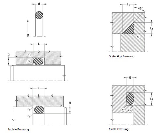
9.2 FUNCTION OF O‑RINGS
The principle is summarised in Fig. 9.2:
- The seal is placed in a groove whose depth g is smaller than the torus diameter d (Fig. 9.2).
- After assembly into the bore, the O‑ring is squeezed and pre‑loaded (Fig. 9.3).
- System pressure acts on the O‑ring and increases the contact pressure (Fig. 9.4).
The initial compression (Fig. 9.3) is essential. Depending on application and material:
- 3 – 20 % for dynamic sealing (hydraulic & pneumatic). In this catalogue the values used are 12 – 14 %.
- 15 – 30 % for static sealing. Here the values used are 17 – 27 %.
9.3 TECHNICAL DATA FOR O‑RINGS
Working pressure, static
- Up to 150 bar for NBR 70 Sh A without back‑up ring
- Up to 500 bar for NBR 70 Sh A with back‑up ring
Linear speed – up to 0.5 m/s
Rotary speed – up to 2 m/s
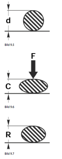
C.S.R. – Compression Set
The compression set measures the time‑dependent elasticity of the elastomer (Figs. 9.5 – 9.7).
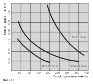
9.4 ALLOWABLE CLEARANCE FOR O‑RINGS
Refer to diagram 9.8 to determine the maximum clearance e: for a given pressure, e must always remain below the values to the left of the curve.
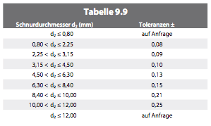
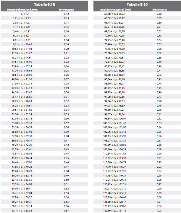
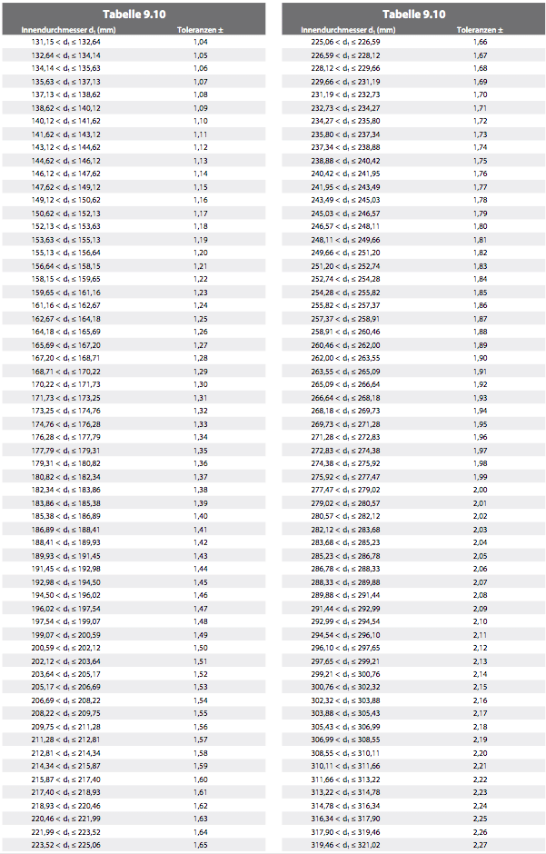
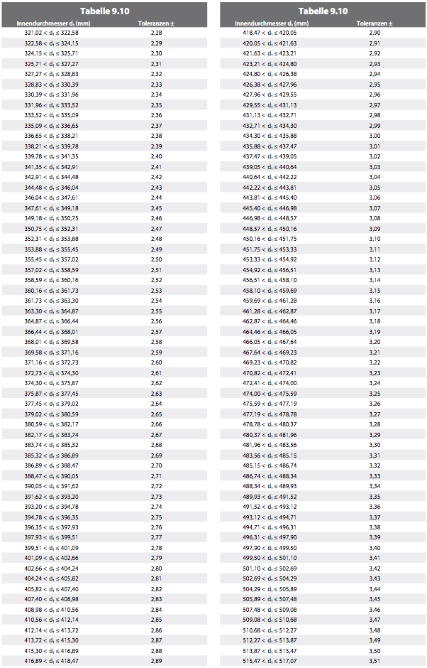
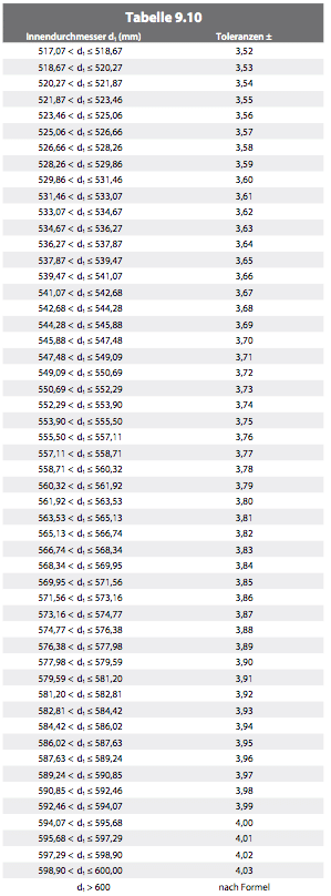
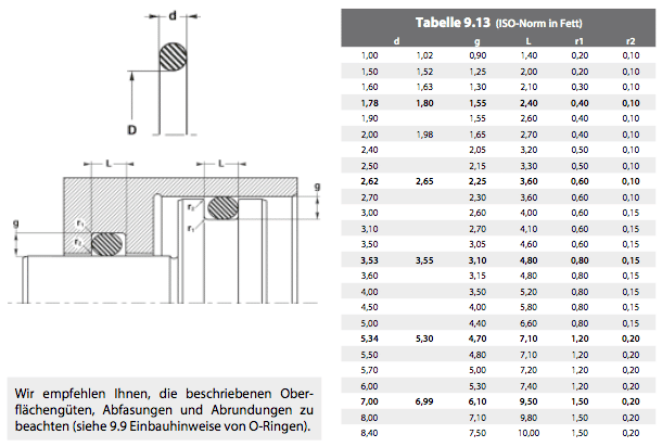
9.5 DIMENSIONAL TOLERANCES TO ISO 3601‑1:2008, CLASS B
Table 9.9 gives tolerances for cord diameters d2.
Tolerances for inside diameter d1 are calculated per ISO 3601‑1:2008 (Class B) using:
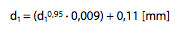
Tables 9.10 – 9.13 provide values up to 600 mm.
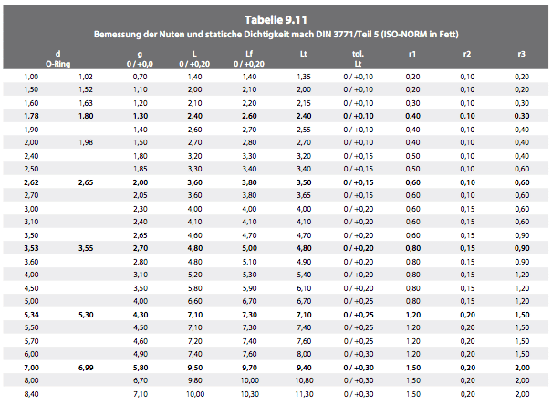
9.6 STATIC SEALING WITH O‑RINGS
9.7 DYNAMIC SEALING FOR PNEUMATIC CYLINDERS
9.8 DYNAMIC SEALING FOR HYDRAULIC CYLINDERS
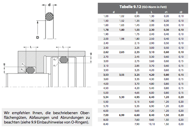
9.9 INSTALLATION GUIDELINES FOR O‑RINGS
Assembly and clearance
We recommend tolerances H7 / f6 for installation. Use diagram 9.8 to set clearance e.
Surface finish
The Ra and Rt values in Table 9.15 must be observed.
Chamfers
Table 9.14 gives the required chamfer lengths.
Radii
Avoid sharp edges. The required radii are given on the following pages.
10. Back‑Up Rings
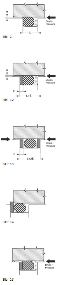
10.1 EXTRUSION
Extrusion occurs when clearance e between parts is too large for the pressure acting on the O‑ring. The O‑ring is gradually sheared and will eventually fail (Fig. 10.1).
The groove width is increased by E – the thickness of the back‑up ring. The back‑up ring is placed opposite the pressure side to support the O‑ring and prevent extrusion (Fig. 10.2). For double‑acting systems two back‑up rings are required (Fig. 10.3).
10.2 PROFILES AND MATERIALS
For both internal and external grooves we prefer endless rings. At high temperatures or with special media, PTFE must be used; rings for external grooves must then be scarf‑cut to allow assembly.
10.3 FURTHER INFORMATION
Although a back‑up ring is a simple part, its selection and dimensioning can be complex:
A – Replacement situations
Existing equipment shows wide variation in groove depths. Initial compression can vary from 10 – 30 %.
Example: Our standard rings BU and PBK. For O‑ring d = 2.62 mm, the ring section is 2.25 mm in PBK and 2.18 mm in BU. Dimensions must therefore be taken with great care, as each manufacturer uses different standards.
- If the ring section is too large, installation becomes difficult or impossible and the ring will wear (Fig. 10.4).
- If the section is too small, extrusion remains a risk (Fig. 10.5).
B – New designs
Standard ranges offered by seal manufacturers are often limited. The same ring is used for static and dynamic sealing.
Example: PBK rings are often used statically but are better for dynamic applications (see Table 9.13). Using PBK statically conflicts with the groove depths we recommend in section 9.9. For dimensions per Table 9.14 we recommend making a DST 108 in H‑PU.
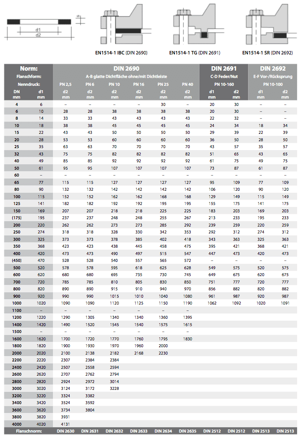
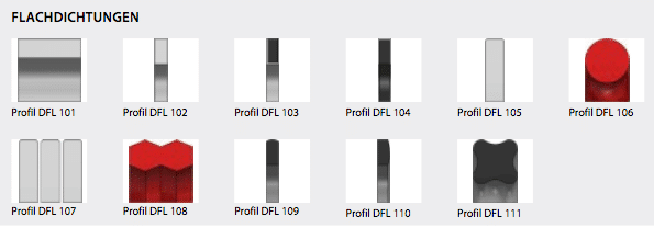
11. Flat Gaskets
11.1 FLAT GASKETS TO EN 1514‑1 (DIN 2690/2691/2692)
11.2 DIMENSIONS AND TOLERANCES FOR GASKET SHEETS, CUT PIECES AND STAMPED ITEMS
12. Seal Express Service
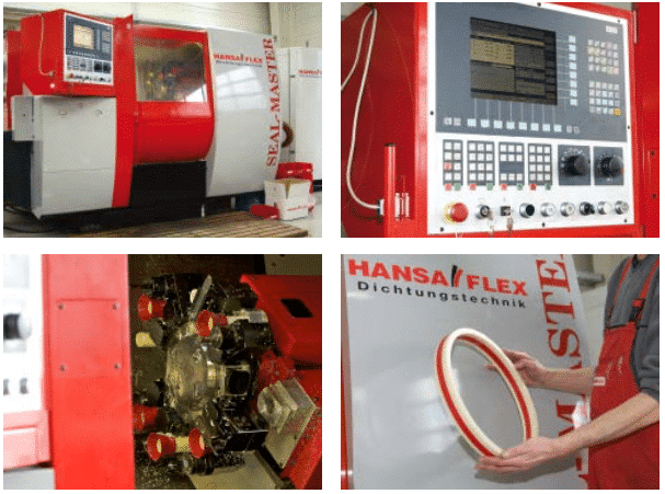
HANSA‑FLEX Seal Manufacturing Centre
With two SEAL‑MASTER CNC units we can produce precision seals and custom plastic or aluminium parts from 5 to 520 mm diameter on demand. Thousands of seal datasets are stored so we can manufacture on a just‑in‑time basis. Almost any seal – standard or special – can be shipped the same day.
Benefits of in‑house seal production
- Custom and standard parts in single or series quantity with highest accuracy
- Software with 100 pre‑programmed standard profiles, adaptable to customer needs
- Standard warehouse with over 11 000 seal types and sizes
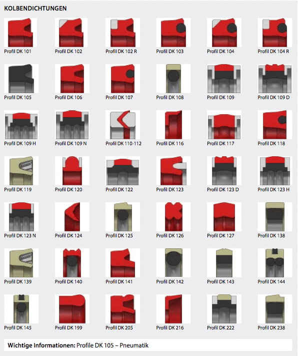
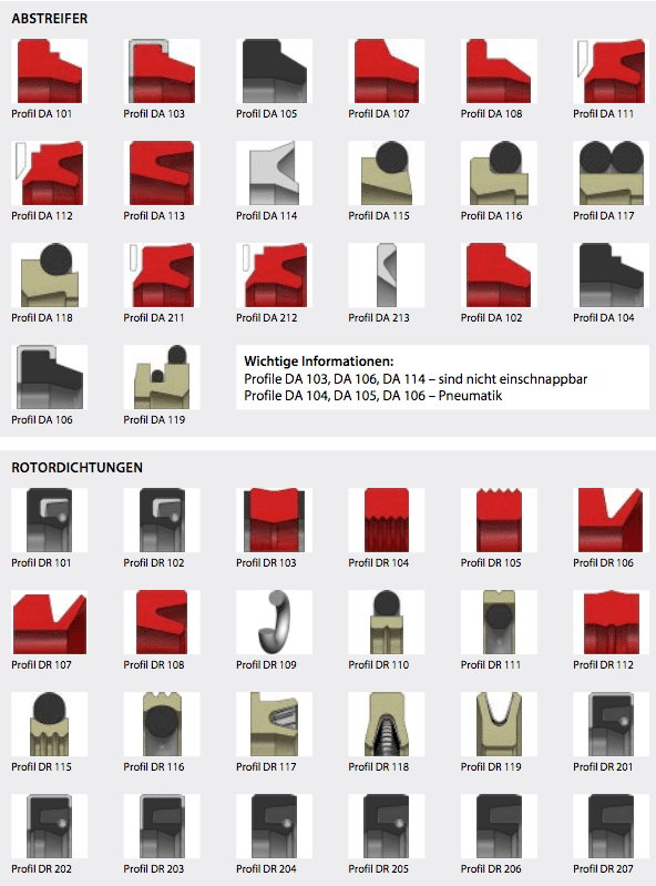
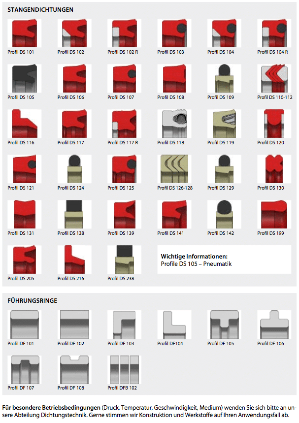
13. Seal Profiles

14. Material Data Sheet