Technical Information
Pneumatic
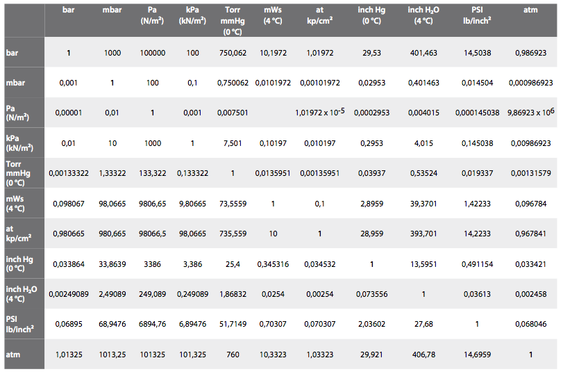
Conversion table for units of pressure
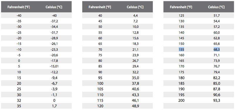
Conversion table for temperatures
Threads and their dimensions
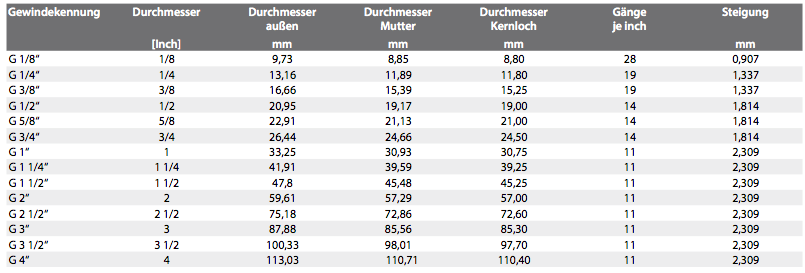
Thread ISO 228
Whitworth pipe thread BSP (British Standard Pipe)
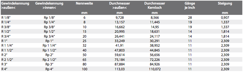
Pipe threads where pressure-tight joints are not made on the threads (cylindrical)
Thread ISO 7/1
Whitworth tapered pipe thread BSPT (British Standard Pipe Tapered) Cylindrical internal thread and conical (cone 1:16) external thread
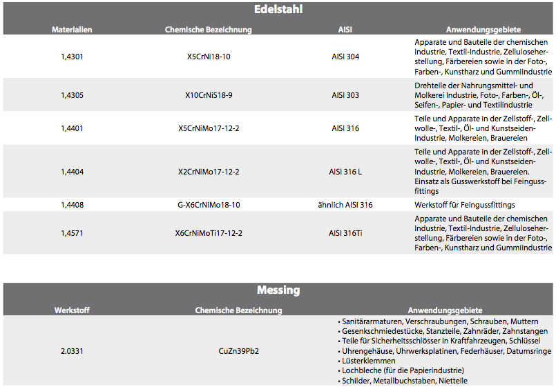
Seal materials
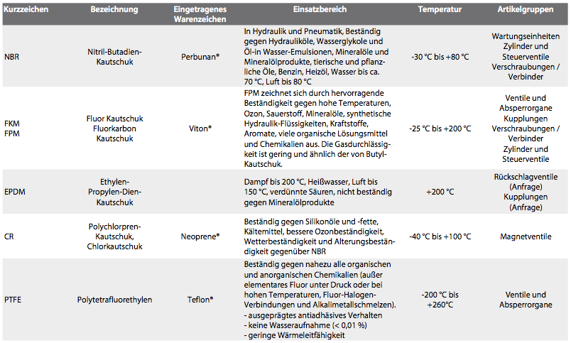
Materials and their fields of use
Air treatment/ Filtering
Compressed air should always be clean enough to ensure that it causes no malfunctions and no damage to the components. Dirt causes higher wear and detrimentally affects the service life of the pneumatic elements.
Any filter in the system will create a flow resistance, therefore, on economic grounds, the filtration efficiency should be matched to the requirements of the application – the air should be as clean as necessary.
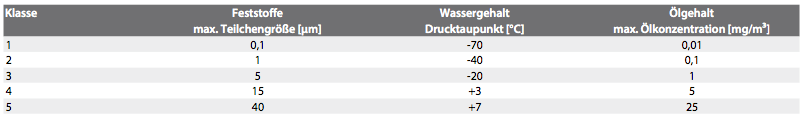
ISO 8573-1 defines different purity classes to allow a consistent assessment of cleaning efficiency to be made. Different requirements apply to the quality of compressed air, depending on the needs of the application. The quality classes should therefore include the following information as per the ordered list below:
Quality class for particles
Quality class for water
Quality class for total oil (droplets, aerosols, vapours)
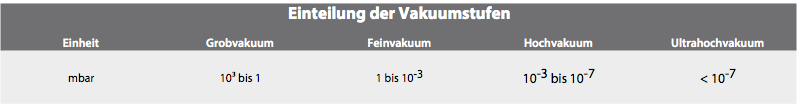
Vacuum
Vacuum is expressed in relation to absolute pressure (absolute zero point).
Designation: - value (negative pressure value) in per cent (%) in the range of 0...1 bar absolute pressure
APPLICATION IN THE FIELD OF COARSE OR OPERATIVE VACUUM AT HANSA-FLEX
Vacuum expressed as a relative value in relation to average atmospheric ambient pressure (approx. 1000 mbar). The vacuum value has a preceding negative sign, because the atmospheric ambient pressure is taken as the zero point. This means that the lowest possible value is -1 bar or 100 % vacuum.
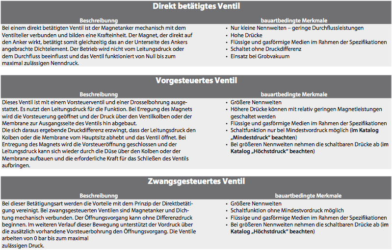
Solenoid valves
Solenoid valves 2/2-3/2-way directional media valves and their methods of actuation:
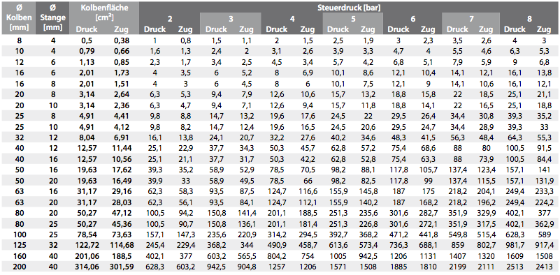
Cylinder forces
Cylinder forces in double-acting cylinders:
Pressure/force tables
Piston force [daN]; 1 daN (10N) = approx. 1 kg
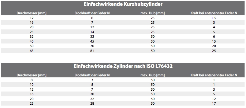
Cylinder forces in single-acting cylinders:
Compressed air pipework system
IMPORTANT INSTALLATION INSTRUCTIONS
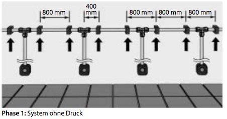
If the system has vertical branch pipes along a wall, it is advisable first to attach the wall brackets only on the pipes running horizontally and then pressurise the installation.
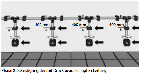
After this, the other wall brackets and the pressurised air points of use (air distribution box) can be fastened in
place.
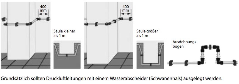
If the pipework extends over a long distance, it is recommended that an expansion bend be provided every 25 metres. Placement around a column requires an adequate distance between the wall and the distribution pipe- work. This is likewise resolved by installing an expansion bend.
Important installation instructions
The user-friendly design of the compressed air pipework system allows it to be installed or removed without any tools at all. As well as the time saved, this can also result in up to 50 % cost savings.
The following points should be observed to ensure a safe and trouble-free installation:
The pipe clamps must be fitted in such a way that there is still enough play to allow the pipe to be displaced.
To avoid damage to the O-rings in the connectors, it is also important to check that the pipe ends are free of burrs.
We always recommend chamfering the pipes to reduce the insertion forces.
To ensure the pipe ends meet at the best angle (90°), they should always be cut using a pipe-cutter.
To prevent pressure losses in the system, the installer must ensure that the pipes are fully inserted into the connectors (look for the marking on the connector).
We recommend keeping the pipework about 30 mm from the wall where the compressed air pipework system passes around a column to allow for the extension in length of the pipes and connectors.
For installations with several vertical pipes, we recommend that the pipe clamps on the horizon- tal pipework are fitted first, then the system be placed under pressure. Only then should the ver- tical pipe clamps and connectors be installed. This ensures that the vertical pipes will remain ver- tical after the installation is complete.
If the compressed air system does not incorporate an air dryer, we recommend the use of our T connector with an integrated water separator. This allows the condensate to be collected at a specific point.
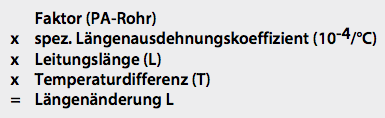
Calculation of the longitudinal expansion of polyamide pipes*
To avoid any undesirable bending of pipes and connections, an accurate calculation of thermal expansion of the
compressed air pipework must be performed before the system is installed.
The plastic pipes change in length by approx. 0.2 mm/°C per metre.
The following factors relating to the longitudinal expansion of polyamide pipes must be taken into account:

Specific coefficient of longitudinal expansion of polyamide = 10-4/°C
The following formula must be used to calculate the longitudinal expansion:
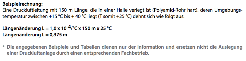
Example of a pipework calculation*
COMPRESSED AIR DISTRIBUTION SYSTEM WITH RING MAIN
The calculation for the ring main is based on half the nominal length of the complete pipework system and the full compressed air requirement. For example: compressed air requirement 1000 l/min, operating pressure 7 bar, complete pipework length would be 300 m as a ring main, therefore the length for calculation purposes would be 150 m.
COMPRESSED AIR DISTRIBUTION SYSTEM WITH BRANCH PIPE
The calculation for the branch pipe is based on the full nominal length of the complete pipework system and the full compressed air requirement. For example: compressed air requirement 750 l/min, operating pressure 7 bar, and the complete pipework length would be 50 m.
* The examples and tables given here are intended for information only and do not replace the design of a compressed air system by an appropriately qualified engineer.
A = pipe length of the ring main in m
B = delivery capacity of the compressor in l/min
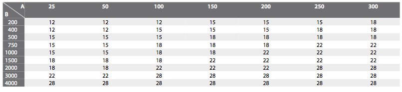
In calculating the lengths of pipe required for the main, supply and branch pipework, we recommend that the supply system is designed as a ring main. This allows the sizes to be calculated based on only half the quantity of air delivered and half the pipework length.
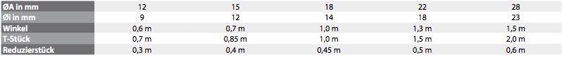
Equivalent pipework length of fittings (per item)
These values must be added to the actual pipe lengths to arrive at the length in terms of hydraulic flowL.
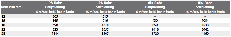
Flow rates for PA and aluminium pipes
The values given for the flow in the main pipe can be changed for flow in each direction.
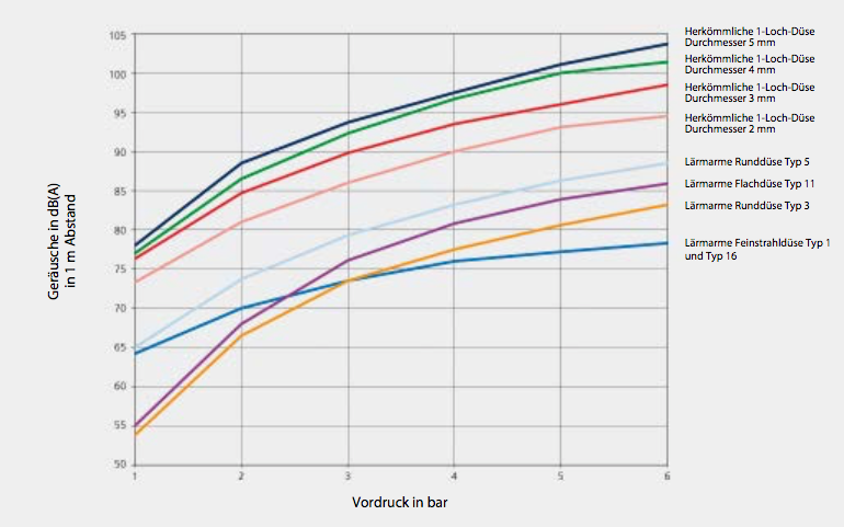
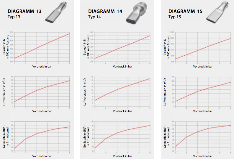
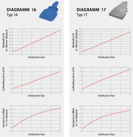
Noise table for saftey nozzles
COMPARED TO STANDARD ONE-HOLE TYPES